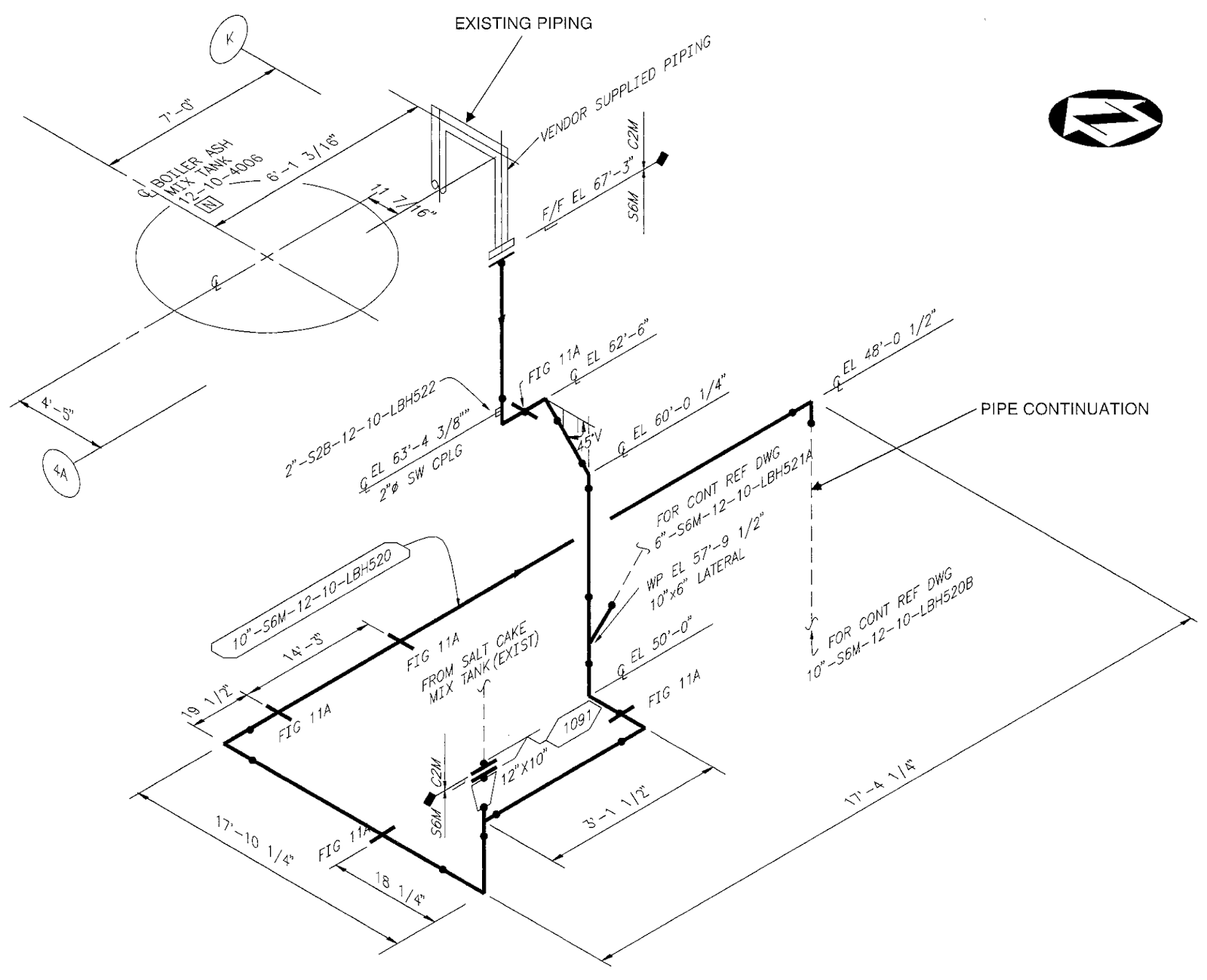
Piping Isometric Drawing Software provides a number of benefits over traditional two-dimensional (2D) CAD programs. This type of software is also known as an “isometric CAD” or “piping design” program.

Vertical pipe lengths are calculated using elevations, while horizontal lengths are calculated using north-south and east-west coordinates.

Pipe lengths are measured using coordinates and elevations. Therefore, dimensions are required to specify exact lengths of piping runs.

The isometric drawing is oriented on the grid relative to the north arrow found on plan drawings and not drawn to scale.

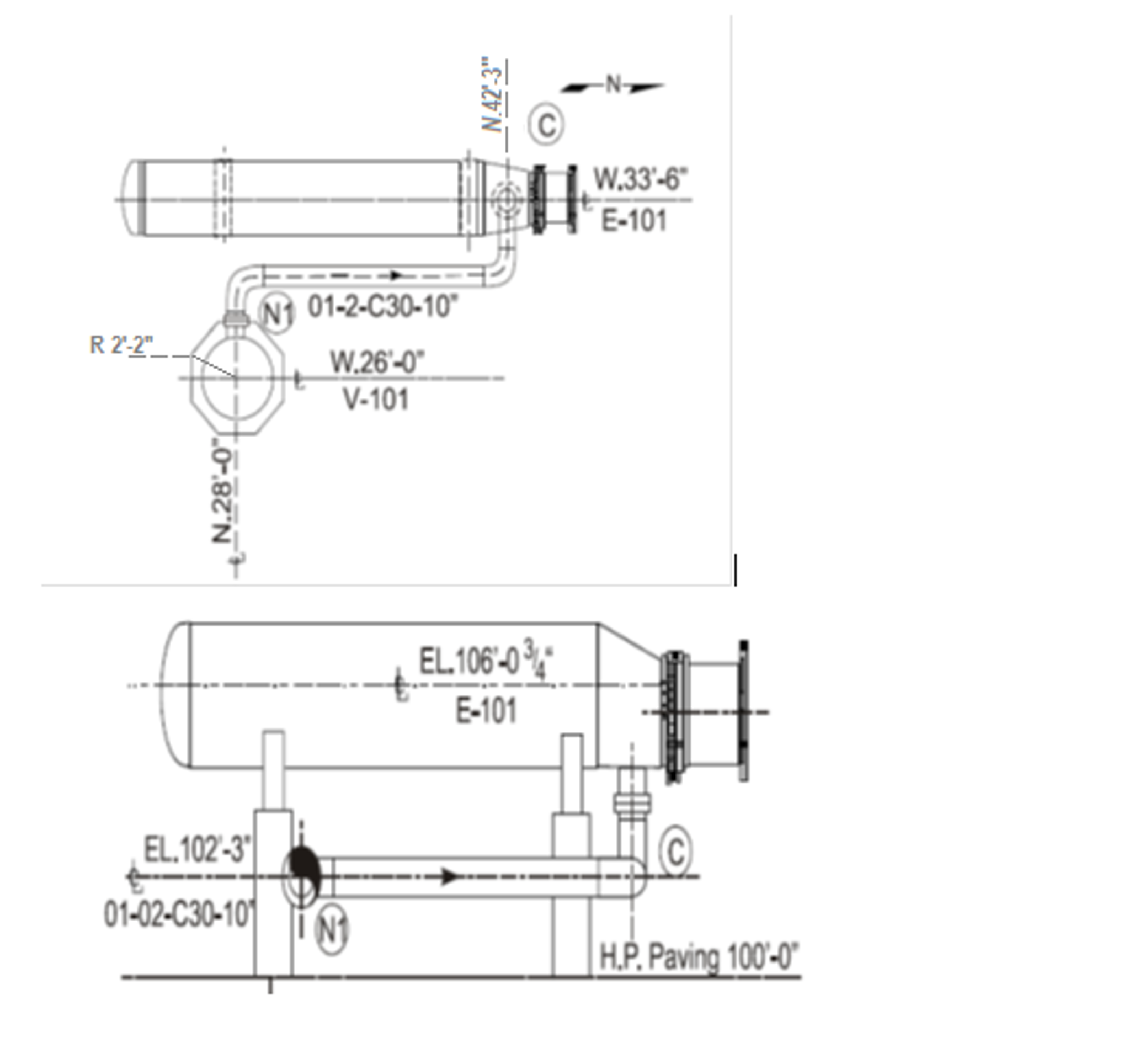
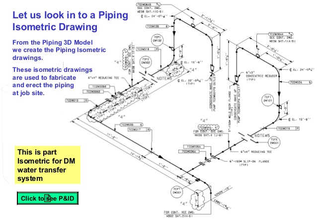
Piping isometrics are usually drawn on a pre-printed paper, with lines of equilateral triangles form of 60°. Symbols like fittings, Valves and flanges are modified to adapt to the isometric grid. The Isometrics drawing are created from information found on a plan and elevation views. In a piping isometrics drawing, pipe is drawn according to it’s length, width and depth, and often shown in a single view.


 0 kommentar(er)
